GCDual Internal Installation for DOL-001 Gamecube
To access the on screen menu hit Left trigger + right trigger + X + Y
Copied from Dansprojects page
Disclaimer:
This is kit is for advanced installers only. I am not held responsible to damage to your console or damage to the kit. Each kit is personally tested by me and confirmed working before being shipped out. This document assumes you know how to take apart the gamecube with a gamebit tool as these instructions will not be included.
This kit uses Zero Force Insertion for the FFC cables. If you are not farmilar with these please visit this site for a visual aid. FFC connectors are fragile and can be broken easily if care is not taken.
This Kit includes:
- QSB PCB
- Main PCB
- HDMI PCB
- FFC cable
- #3-56 Nut
- M2 Screw
- M2 Nut
- 30 AWG Wire
Items required:
- Temperature Controlled Soldering Iron
- Flux
- Extra Fine Soldering Tip
- Solder Wick
- 99% Isopropyl Alcohol
- Side Cutters
- Drill Bit
- Drill
- Sharpie
- Small Square File
- Small Flat File
- Metal Cutting Tool, ie dremal
5.2 and Earlier Revisions:
For scart To hookup RGBS you will need a SNES mutlitout cable with a sync attenuation resistor inside the cable. Depending how you wire the QSB will depend on which cable you need. But most users should need a CSYNC cable like these:
https://retro-access.com/collections/super-nintendo/products/super-nintendo-stereo-rgb-scart-lead-snes-csync-full-shield-grounded-cable
https://www.retrogamingcables.co.uk/nintendo/super-nintendo/super-nintendo-entertainment-system-famicom-snes-n64-rgb-av-scart-cable-ntsc-tv-lead-wire-cord
5.3 and later Revisions:
Both types of scart cables are supported. If you cable has an attenuation resistor inside, then make sure JP2 is closed/shorted. If your cable does NOT have an attenuation resistor then make sure JP2 is open. These cables with attenuation resistors are still recommend on 5.3 and later.
https://retro-access.com/collections/super-nintendo/products/super-nintendo-stereo-rgb-scart-lead-snes-csync-full-shield-grounded-cable
https://www.retrogamingcables.co.uk/nintendo/super-nintendo/super-nintendo-entertainment-system-famicom-snes-n64-rgb-av-scart-cable-ntsc-tv-lead-wire-cord
All Revisions:
To Hookup HDMI you will need an HDMI mini cable. I recommend this one on amazon: https://www.amazon.com/AmazonBasics-High-Speed-Mini-HDMI-HDMI-Cable/dp/B014I8UEGY/
Step 1. Don’t skip this step. Make sure you know how the jumpers work.
Decide how you want to wire the GCDual up the analog port. There are jumper pads on the QSB PCB that will allow you to route signals to different locations. Click here refer to this document to understand the jumper settings. This document also goes over required steps for PAL consoles and NTSC consoles wanting to use the CHROMA and LUMA pins.
Step 2.
- Dissamble the gamecube, so the motherboard is free.
*Leave the heatsink in place, unless you plan to replace thermal pads. - Desolder the highlighted areas with desoldering braid.
Install the original heatsink screw with the supplied #3-56 Nut into the hole closest to the digtal port.
Don’t overtight or you will strip the screw.

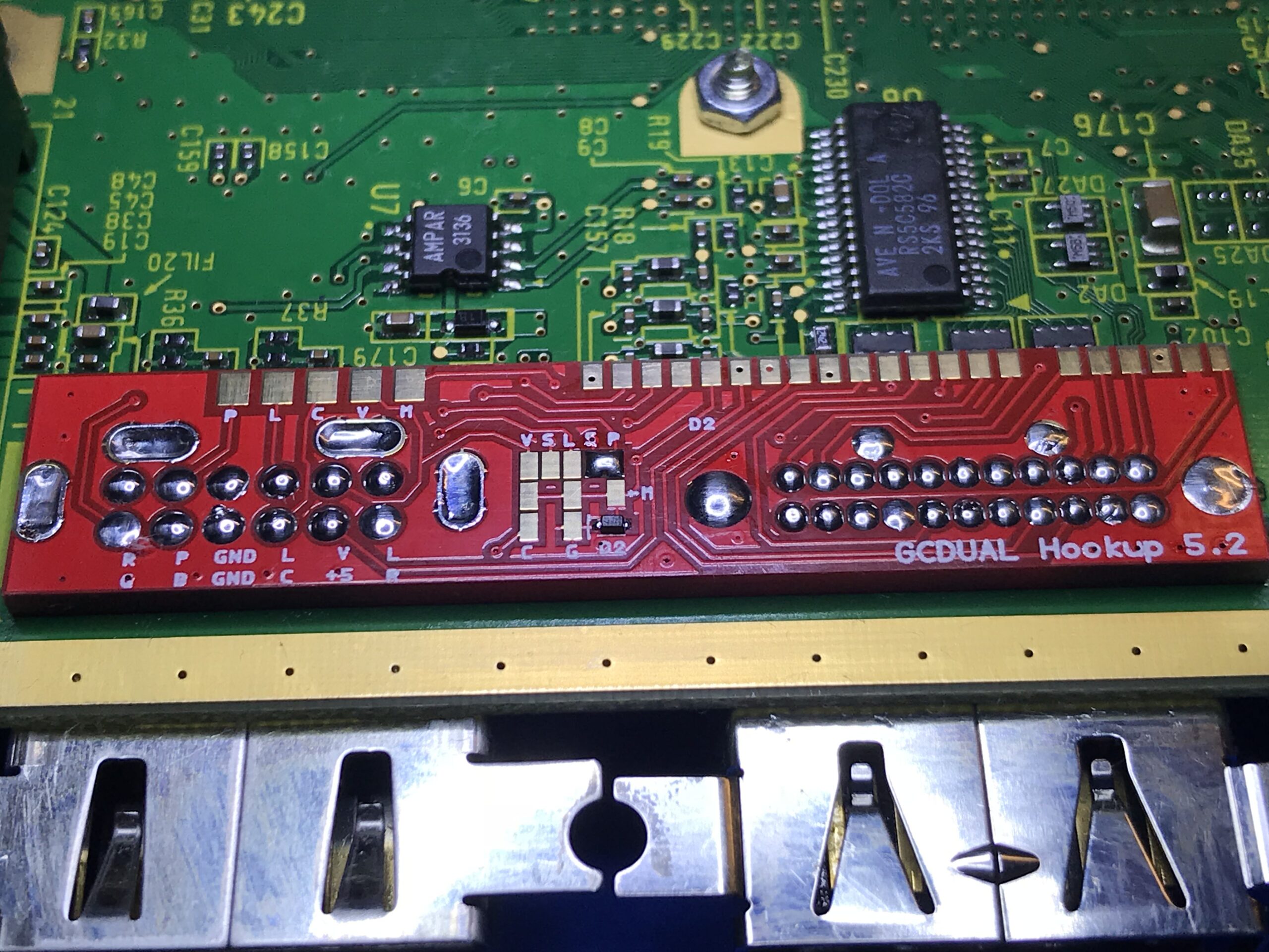
- It should look like this when done.
- The QSB should lay perfectly flat. If it does not desolder some more.
- Solder in the QSB.
Make sure you get good penetration into the holes.
- I use a soldering tip like this. It works very well.
- Check to verify there is NO continuty between adjacent pins
- Check to verify there is continuty between QSB points and digital out
this is is a little difficult at first, but is eaiser than it looks.


Step 3.
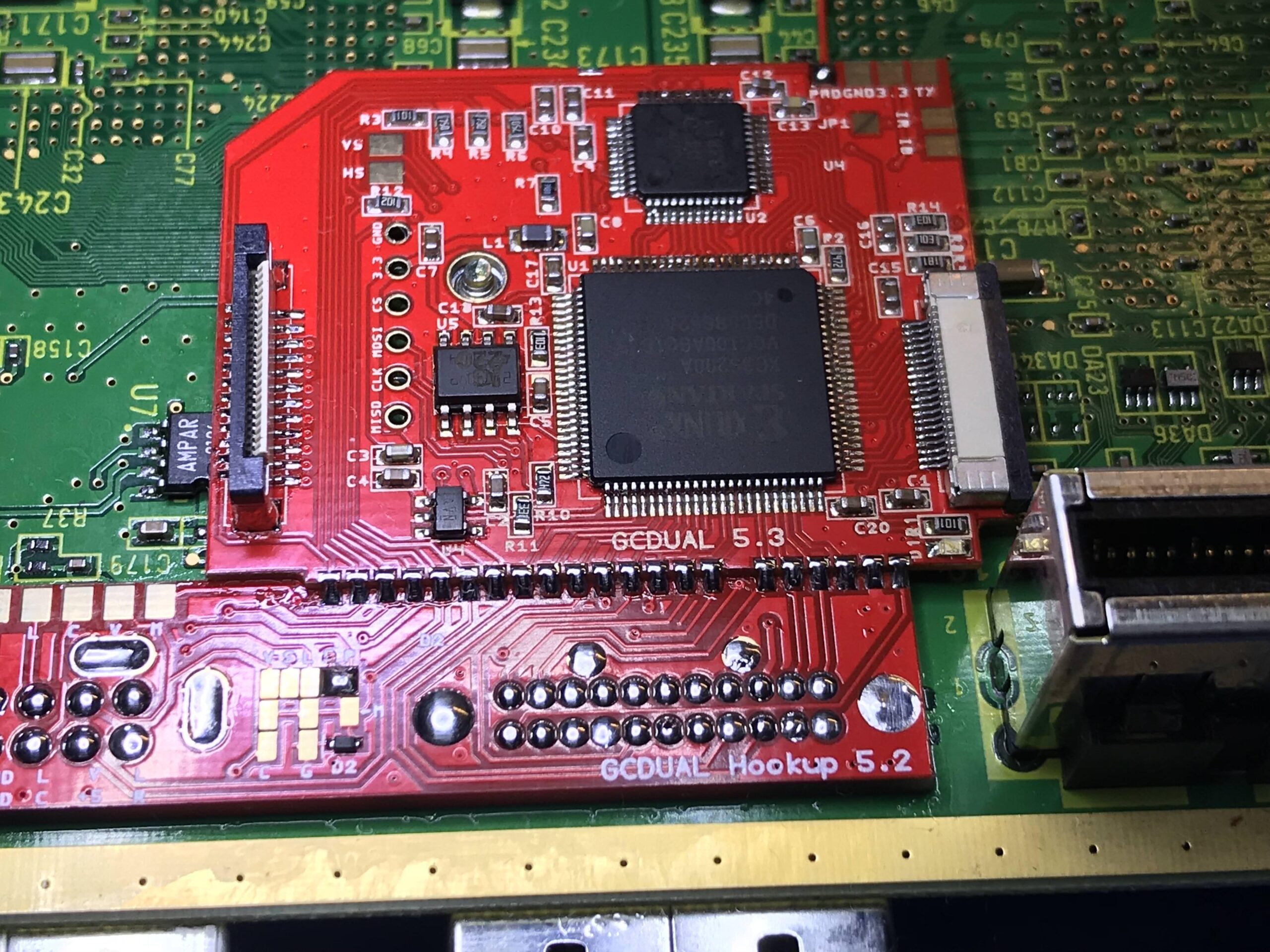
- Line the pcb up so the screw is centered, and the pads are even, and tack into place.
- Solder the rest of the pads in. Go slow, don’t bridge pins.
Check to verify there is NO continuty between adjacent pins
The RGB lines are tied to ground with 75 Ohm resistors. So you may continuty to ground and each other
- Solder the support
- Solder the Pad wire in
- Attach the FFC Cable
FFC connectors are fragile, be careful


Step 4.
- Remove the metal material highlighted in yellow.
- It should look like this when done.
- Reinstall the bottom metal shield and motherboard into the case. and attach the other 5 screws into the heatsink
- Reinstall the DVD-ROM and route the FFC cable like so.


Step 5.
- Insert the HDMI PCB into the pocket and trace around the top of the HDMI connector. Drill 3-4 consecutive holes below the sharpie marking
- Use a small file (I use flat and sqaure tools); Slowly file away, checking the piece multiple times for fitment.
- Drill a small hole, and insert supplied M2 Screw, washer and nut
- It should look like this once done.
- Install the FFC connector into the HDMI PCB
This is harder than it looks, just be careful and take your time, also note the orientation.
- Attach the back piece and reinstall the top case.
Make sure not to pinch the FFC cable as you slide the top case on.


You’re done
If you don’t get video, try another tv. If still no luck enter the trouble shooting section.
Trouble Shooting
Most issues are related to the QSB installation on the main board. However here are some basic troubleshooting steps.
First setup the gamecube so its possible to run the without the case on.
You can do this by removing the motherboard and laying it on the heatsink. Then you can remove the power board from the case and plug it directly into the motherboard. It will look similar to this. Now you are able to power the unit and test without constantly taking the machine apart and back together.
When video does appear you will get an error message at bootup, don’t be alarmed, this is because the there is no dvd drive. Also don’t let the unit run for a long time like this. Becareful as you are messing around with a live power supply. I’m not responsible if you fry your Gamecube.
With video problems boot up and see if the led is off, solid or blinking.
- Led is off – FPGA is not booting, check voltage (+3.3) on qsb (+5 is only used for HDMI signal detection from TV)
- Led is solid – Clock signal is grounded or not connected (Check CLK)
- Led is blinking – FPGA has detected the clock (Check all VD# and CSEL points)
With your specific issue in mind, check your QSB and the corespoding points. You will need to do: check for shorts between points, reflow connections to make sure there is good contact.

If you have issues with audio, as in no sound or garbled audio. Verify points LRCK, ADAT, BCLK are connected properly.
For questions about GC-Video’s functions refer to the github here
GCVideo License:
Copyright (C) 2014-2017, Ingo Korb <[email protected]>
All rights reserved.

Redistribution and use in source and binary forms, with or without
modification, are permitted provided that the following conditions are met:

1. Redistributions of source code must retain the above copyright notice,
   this list of conditions and the following disclaimer.
2. Redistributions in binary form must reproduce the above copyright notice,
   this list of conditions and the following disclaimer in the documentation
   and/or other materials provided with the distribution.

THIS SOFTWARE IS PROVIDED BY THE COPYRIGHT HOLDERS AND CONTRIBUTORS "AS IS"
AND ANY EXPRESS OR IMPLIED WARRANTIES, INCLUDING, BUT NOT LIMITED TO, THE
IMPLIED WARRANTIES OF MERCHANTABILITY AND FITNESS FOR A PARTICULAR PURPOSE
ARE DISCLAIMED. IN NO EVENT SHALL THE COPYRIGHT HOLDER OR CONTRIBUTORS BE
LIABLE FOR ANY DIRECT, INDIRECT, INCIDENTAL, SPECIAL, EXEMPLARY, OR
CONSEQUENTIAL DAMAGES (INCLUDING, BUT NOT LIMITED TO, PROCUREMENT OF
SUBSTITUTE GOODS OR SERVICES; LOSS OF USE, DATA, OR PROFITS; OR BUSINESS
INTERRUPTION) HOWEVER CAUSED AND ON ANY THEORY OF LIABILITY, WHETHER IN
CONTRACT, STRICT LIABILITY, OR TORT (INCLUDING NEGLIGENCE OR OTHERWISE)
ARISING IN ANY WAY OUT OF THE USE OF THIS SOFTWARE, EVEN IF ADVISED OF
THE POSSIBILITY OF SUCH DAMAGE.</[email protected]>