Watch me do the installs on YT first! LCD install:
Full case install:
1. If doing an LCD install, set the breakout pcb on ram chip: Watch this part to see why it’s placed here: https://youtu.be/_TxVRt-11B0?t=1753
If doing a Full Case install, set the breakout pcb on CPU:
Double sided foam tape works great for LCD install. Double sided non foam tape or hot glue works well for full case install.
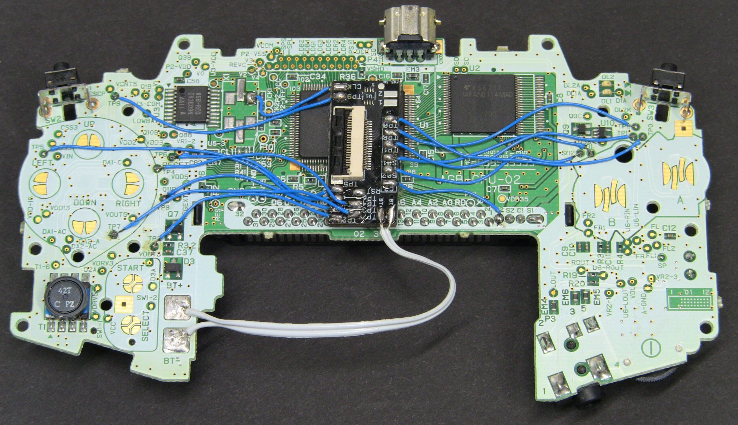
2. Using the hookup wire included in the kit or your own wire, attach lengths as short as possible between each pad. On LCD installs try to avoid these areas! This is an older pic so don’t pay attention to the breakout pcb placement etc.
Do not hook up pads 1, 2, or RST of the breakout pcb! All other pads are identified and match a pad on the GBA mobo.
The GBA test point pads (TP*) are small and fragile, they will lift easily if they get too hot! So use a little as heat as possible!
On full case installs you can solder to the larger pads on the GBA mobo that would normally be covered by the rubbers, pics coming, but it’s easy to figure out with a meter what test point pad is connected to what larger contact pad. I prove a couple out in this vid: https://youtu.be/_TxVRt-11B0?t=1656
4. 3″ of 28awg 2 conductor ribbon cable is provided for power and ground, BT+ and BT-, aka battery positive and negative. Don’t get them mixed up!